Engine Rotors
Racing Beat's carbon apex seals for high RPM and racing applications.
Engine Rotors
All Mazda rotors consist of two (2) main pieces: the basic cast iron rotor and the steel rotor gear that is held in the basic rotor by 9 or 12 roll pins.
Over the years, Mazda has reduced the weight of the rotor assemblies in an effort to improve performance. Up until the introduction of the RX-8, the 1989-95 rotors were the lightest production rotors and can still be installed in the 1986-88 engines if you also include the matching front and rear counterweights. However, the 1986 and later rotors should never be used in 1985 and earlier engines due to geometry and compression ratio differences.
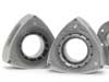
The rotors used in the turbo engines are lower compression, as compared to their non-turbo counterparts- 8.5:1 vs. 9.4:1, respectively (1986-88 models); and 9.0:1 vs. 9.7:1 respectively (1989-95 models); and 10:1 (RX-8). (See Photo)
Only one style of rotor is available for the 1974-85 13B engine. However, 1974-75 12A engines have a symmetrical combustion chamber (and will interchange front-to-rear) while 1976-85 rotors were asymmetrical in the combustion depression. The power difference between the 12A rotors is negligible (at optimum ignition timing) except for one factor - the 1984-85 model was lighter. Therefore, the 1984-85 12A rotor is the best choice.
Material can be removed from any rotor to further lighten it while retaining the strength necessary for high RPM operation. We utilize a CNC machining process to produce our Super Light-Weight Rotor assemblies that are packaged as a completely balanced unit, including retained rotor gears, and front and rear counterweights.
If you do not intend your engine to run above 8,500 RPM the stock rotor is satisfactory, requiring only a careful inspection of the seal and bearing clearances, as well as the maximum width of the rotor.
If your engine will run near or above 8,500 RPM for extended periods of time, the rotor gears will very likely "move away" from the basic rotor. Since the stock rotor side clearance is about .005", little movement is required to jam the rotor between the side housings, causing damage. While it is possible to tap the gears back down with a plastic hammer, the problem will persist until the rotors are replaced with retained rotor gear components.
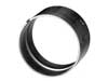
The process of retaining rotor gears involves the removal of the rotor gear and the cutting of a matching groove in both the outside diameter of the gear and in the recess of the basic rotor where the gear sits. A snap ring, similar in appearance to a piston ring, is installed on the gear before it is pressed back into its rotor recess, thereby permanently locking the gear in place. (See Photo)
This process was originally developed by Mazda for use on racing engines. The virtue of retaining rotor gears with snap rings, as opposed to other methods, is that it retains the slight flexibility originally intended between the rotor gear and basic rotor, thereby reducing the shock loads on the bearings and stationary gears.
The RX-8 rotors can be used in earlier non-side exhaust port engines. They are lighter and have a 10:1 compression ratio. The "notches" located on each rotor flank at the trailing port of the combustion chamber change side intake porting slightly, but have no effect on a peripheral port engine. The only problem is that these rotors must be used with an RX-8 eccentric shaft and balance weights, or be re-balanced with other components.
When assembling a Renesis engine it is critical to install the engine rotors in their correct housing. To determine which are the "front" and "rear" rotors, place one rotor in front of you, flat on the table, gear side up. Rotate it until one apex seal is pointed "up" (away from you) relative to the other two. If the small "chamfer" on the edge near the apex seal is to the right of that seal, that is the "front" rotor - as situated in the stock car. If not, this is the rear rotor.
Rotor Clearancing
A second concern for rotors used near or above 8,500 RPM is the clearance between the sides of the rotor and the side housings. The construction and assembly of the rotor and rotor gear is such that both sides of the rotor have a portion, referred to as the "land", that protrudes out from the rotor "side" several thousandths of an inch. For measuring purposes, detailed below, the "land" on the side of the rotor containing the rotor gear is the face of the rotor gear itself. The "land" on the opposite side of the rotor is the circular portion of the rotor surrounded by the inner oil seal. These features need to be taken into consideration when clearancing the rotor.
The first step in preparing a rotor for clearancing is to measure the thickness of the rotor housing being paired with the rotor at eight evenly spaced points to determine the minimum or narrowest point of thickness of the rotor housing. This minimum thickness becomes the "base line" for the calculation process.
Now, measure the thickness of the rotor and rotor gear assembly at three different points from the "land" on one side to the "land" on the other side. Select the maximum, or widest, thickness of this assembly and subtract this number from the base line number previously obtained. We have found that the following clearances work well:
Clearance between side housings and rotor maximum "land" width:
12A Engines (.009" +/- .001")
or 13B Engines (.010" +/- .001")
"Land" protrusion from rotor side: .0055" +/- .0005" (each side). This "land" clearance is obtained by machining away material from the "side" of the rotor, thus leaving the "land" extending from the rotor "side" by the specified amount.
It is entirely possible, based on the production tolerances we have seen over the years that you may need to remove as little as .001" to. 002" from each surface to achieve the recommended clearance. In other words, some of the clearance required already exists.
Rotor Bearings
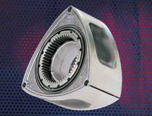
All rotor bearings, stock or Mazda Factory Race (MFR), are made from a flat piece of steel which is stamped, rolled, and hooked together at the joint with a "puzzle lock" design. This bearing is then coated with copper and plated with about .0015" of Babbitt bearing material. The inside surface of the puzzle lock joint area is ground off to eliminate high spots, usually resulting in a portion of the copper coating being exposed. This appears, to the untrained eye, to be a worn spot on the bearing, but is in fact normal (See Photo).
Rotor bearings do cause occasional problems during high RPM operation. It is important to use properly clearanced rotor bearings. In general, do not replace rotor bearings when you are re-using rotors unless they are over the recommended clearance or show some damage from dirt, heat, or lack of oil. Our experience has shown that used bearings in good condition are safer than new, untried bearings.
For most purposes, there are only two choices of rotor bearings (technically, there are other models for the 13G 3-rotor, and to fit a 13G rotor to a 13B eccentric shaft, but these are relatively rare). Both 12A and 13B rotors use the same bearing. The two choices are the stock bearing and the MFR bearing.
For high performance street and racing use, the best rotor bearings we offer are Mazda Factory Race (MFR) rotor bearings with a deep oil groove and additional clearance (approximately .0005" extra). While stock bearings can be grooved deeper and polished to obtain additional clearance, the MFR bearings are still the better choice. The MFR groove is approximately .070" deep to provide an improved reservoir of oil around the bearing.
Up to 8,500 RPM, .003" +/- .0005" eccentric shaft-to-rotor bearing clearance is acceptable. Beyond 8,500 RPM, clearance should be .004"+/- .00025". Clearance can be adjusted by polishing the inside of the rotor bearings with 400 grit or 600 grit wet-or-dry sandpaper strips which are spun with a high speed motor such as an air powered die grinder.
Copyright 2007-2024 Racing Beat, Inc ©